
-
Home
- About Us
- Products
- Application scenarios
- Download
- News


 Classify
- Company News
- Industry News
- FAQ
Industry News
Gas flow transducers in oxygen concentrators
2026-09-03Gas flow transducers in oxygen concentratorsGas flow transducers in oxygen concentrators
The core function of the ultrasonic gas flow transducer in an oxygen concentrator is to simultaneously measure oxygen concentration and flow rate. It calculates the flow rate using the time difference method (the time difference of ultrasonic wave propagation in the forward and reverse directions) and infers the oxygen concentration based on the variation in sound speed, thereby enabling closed-loop control of the oxygen concentrator.
To ensure the ultrasonic gas flow transducer maintains stable and accurate measurement in the oxygen concentrator, attention must be paid to installation, selection, and maintenance
1. Installation
Ensure straight pipe sections: Sufficient straight pipe sections are required upstream and downstream of the transducer to avoid airflow turbulence affecting accuracy. The conventional requirements are ≥10 pipe diameters upstream and ≥5 pipe diameters downstream. If there are flow-disturbing components such as elbows or valves upstream, the straight pipe sections must be further extended.
Avoid turbulence and interference: Install the device away from components that generate turbulence, such as valves, pumps, and elbows, and also stay clear of strong electromagnetic interference sources like frequency converters and high-power motors to prevent signal instability.
Pipe condition: The inner wall of the pipe at the transducer installation location must be smooth, free from rust, scaling, or severe corrosion pits, as these would attenuate the signal and lead to measurement inaccuracies. During installation, evenly apply the coupling agent to the transducer surface and eliminate any air gaps.
Installation Orientation: The transducer should be installed within a 45° range in the horizontal direction of the pipeline, avoiding placement at the top or bottom to prevent gas or impurities from entering the sound path and affecting measurement.
2. Selection and Usage
Flow velocity matching: Gas ultrasonic flow meters have an ideal working flow velocity range. If the flow velocity is too low, the error will increase, while excessively high velocities may cause the signal to be "blown away." When selecting a model, it is essential to base the choice on the actual oxygen output flow rate and pipe diameter of the oxygen generator to ensure the flow velocity falls within the appropriate range.
Acoustic interference: If the oxygen concentrator contains high-speed pressure-reducing equipment or sound-absorbing devices, it may generate frequencies close to the operating frequency of the transducer
Ultrasonic interference can cause measurement anomalies, so it is important to avoid or implement soundproofing measures during component selection.
Regular maintenance: The transducer surface is prone to impurity or scale deposition, which can cause signal attenuation. Regular cleaning and inspection are required, along with checking for proper line connections and normal zero-flow measurement.
3. Pay attention to signal drift
Temperature effect: The propagation speed of ultrasonic waves in gases varies with temperature. Prolonged operation of the oxygen concentrator leads to internal temperature rise, which directly causes deviations in sound speed calculations and results in drift in concentration and flow readings.
Transducer resonance deviation: Prolonged vibration, aging, or environmental temperature variations can cause the actual resonant frequency of the transducer to deviate from the factory-set value, resulting in reduced driving efficiency and unstable signal amplitude.
Medium contamination: Molecular sieve powder and water vapor adhere to the acoustic surface of the transducer, altering the sound wave coupling state and causing a systematic deviation in the time difference of forward and reverse propagation.
Circuit parameter drift: The sampling resistor of the main control unit and the components of the driving circuit undergo parameter variations over time, resulting in inaccurate current and time sampling data.
4. Signal Drift Calibration
Resonance frequency automatic sweep calibration: The host computer first defines a narrow sweep range centered around the nominal resonance frequency. The main control unit adjusts the driving frequency in fixed steps, simultaneously collecting the transducer current sampling values at each frequency point, calculating the corresponding impedance data, and identifying the actual resonance frequency corresponding to the minimum impedance point. The updated frequency is then written to the main control unit's memory to complete the update.
Power Segmentation Calibration: Divide the commonly used 0~10L/min flow range of oxygen concentrators into multiple target power levels. At the locked actual resonant frequency, output the target power level by level, collect the corresponding output voltage values, and generate a "target power-voltage" mapping table stored in the main control unit. During subsequent operation, directly query the table to output the corresponding drive signal.
Impedance Dynamic Calibration: The system automatically collects the transducer impedance values under two different drive currents, performs weighted calculations to obtain the current actual impedance, automatically adjusts the excitation current output, compensates for amplitude deviations caused by transducer performance degradation, and ensures measurement stability.
Standard gas matching and calibration: Introduce a standard oxygen gas with a known concentration (e.g., 93% standard gas), and adjust the time difference baseline under both zero flow and rated flow conditions to quickly eliminate system cumulative deviation.
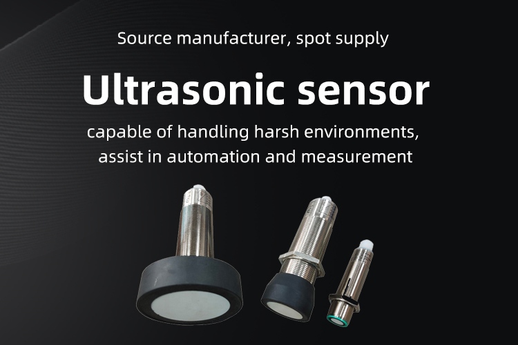
Mic Metering offers 200KHz and 500KHz ultrasonic gas flow transducers with excellent consistency and high sensitivity. For detailed product information, please visit www.micmetering.com
Links:Service Hotline
+86 13923792185
Website:www.micmetering.com
Address:6th Floor, Block B, Area A, Qinghu Science and Technology Park, Longhua District, Shenzhen, Guangdong Province
Copyright © 2025 MIC Metering (Shenzhen) Limited 粤ICP备2025358196号-1 Cookies Policy-
Service Hotline
Service Hotline
+86 13923792185
-
WeChat

-
TOP
Our Cookie Usage Policy
Our website uses cookies and other similar technologies to distinguish you from other users of our website. This helps us provide you with a good experience when you browse our website and allows us to improve our website. For more information, please refer to our Cookie Policy. - About Us