
-
Home
- About Us
- Products
- Application scenarios
- Download
- News

 Classify
- Company News
- Industry News
- FAQ
Industry News
How to select variable reluctance resolver
2026-09-03How to select variable reluctance resolver
I. Principle of Variable reluctance resolver
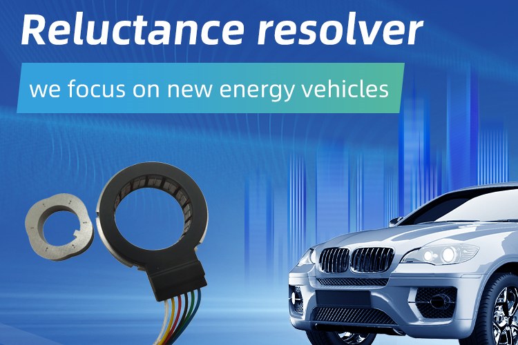
Variable reluctance resolver is a sensor used to test the angle between the rotor and stator of a motor. It is also composed of a stator and rotor, with stator distributed excitation winding and sine cosine feedback winding. The rotor is made of stacked silicon steel sheets. When in use, its rotor is coaxial with the motor rotor. When a sine wave excitation signal is applied, the rotating rotor will change the magnetic resistance of the magnetic circuit, ultimately affecting the amplitude of the sine and cosine winding feedback signal. Then, the principle of measuring the angle of a rotary transformer is to separate the angle information contained in the signal.
II.Selection of Variable reluctance resolver
1. Selection of pole pairs: Generally, the same number of poles as the motor pole pairs is selected, so that the measured electrical angle does not need to be converted to the electrical angle of the inverter coordinate transformation. Of course, as long as the measurement of electrical angle error meets the requirements, it is also possible for the pole pairs of the two to be mismatched. If the motor has 4 poles and the Variable reluctance resolver has 2 poles, then when the Variable reluctance resolver rotates 90 degrees, the corresponding electrical angle of the motor is 180 degrees, and vice versa. Theoretically, the higher the number of pole pairs, the smaller the electrical error
2. Selection of transformation ratio: The current mainstream excitation signal amplitude is 7Vrms/4Vrms, and the feedback signal is finally input into the decoding chip for decoding. For cost reduction and simplicity, it is necessary to ensure that the selected transformation ratio ensures that the amplitude of the feedback signal is within the input range of the chip and close to its recommended value. In the field of new energy vehicles, the transformation ratio is 0.286.
7Vrms corresponds to 19.8Vpp, so at a transformation ratio of 0.286, the amplitude of the feedback signal corresponds to 5.66Vpp, which exceeds the recommended input range of the decoding chip. At this point, the requirements can be met by adjusting the amplitude of the excitation voltage (in fact, for personal applications, it is recommended that the excitation voltage be less than the recommended value in the manual. The benefits are as follows: low excitation voltage requires less driving current, making it easier to design circuits and improving reliability accordingly. In addition, low excitation voltage results in low residual voltage, which can reduce electrical errors to a certain extent. As for the benefits of high excitation voltage, it is high signal-to-noise ratio and ensures that the established magnetic field is strong enough. However, from the perspective of design testing and cost evaluation of adjusting feedback circuits, the disadvantages outweigh the advantages).
3. Installation dimensions: Measure the available installation space of the motor, determine the outer diameter and installation method of the rotary stator (such as frameless, split type, etc.).
• Inner diameter of rotor (shaft diameter): The inner diameter of the rotary variable rotor is determined based on the diameter of the motor shaft and can usually be customized.
• Maximum speed: The rated maximum speed of the selected rotary transformer must be higher than the maximum working speed of the motor.
III. Electrical parameters of Variable reluctance resolver
1. Excitation frequency: Recommended frequency is 10kHz/16.5kHz. If the frequency is too low, the input impedance will be low and the required driving power will increase. Furthermore, with low frequency, there is less angular information carried at high speeds, which cannot meet the application requirements. Excessive frequency mainly increases the value of residual magnetic voltage, which has an impact on hardware decoding speed and bandwidth. It is not recommended to make changes, and the maximum frequency should not exceed 20kHz.
2. Electrical error: used to measure the degree to which the output electromotive force strictly conforms to the sine cosine relationship with the rotation angle, expressed in angular minutes and angular seconds.
3. Impedance: The input impedance is closely related to the excitation power, and the output impedance can be ignored (the receiving load of the rotary decoding chip is much larger than the output load of the rotary converter, and there is basically no power loss). The main component of input impedance is resistance, and the impedance angle is generally less than 10 °. The driving power can be approximately calculated directly by the square ratio of the effective value of the excitation voltage to the input impedance.
4. Phase shift and residual pressure: The former represents the deviation angle between the excitation signal and the feedback sine signal, while the latter represents the magnetization degree of the magnetic steel, mainly related to the material.
Due to its simple structure, brushless, non-contact, and extremely high reliability, Variable reluctance resolver is particularly suitable for the following harsh environments:
Temperature range: Vehicle grade typically requires -40 ℃ to+155 ℃.
Anti vibration and anti impact: It has obvious advantages in strong vibration scenarios (such as electric vehicle drive motors).
Typical applications: New energy vehicle drive motors, electric power steering systems (EPS), high-speed motors and servo systems, etc.
Links:Service Hotline
+86 13923792185
Website:www.micmetering.com
Address:6th Floor, Block B, Area A, Qinghu Science and Technology Park, Longhua District, Shenzhen, Guangdong Province
Copyright © 2025 MIC Metering (Shenzhen) Limited 粤ICP备2025358196号-1 Cookies Policy-
Service Hotline
Service Hotline
+86 13923792185
-
WeChat

-
TOP
Our Cookie Usage Policy
Our website uses cookies and other similar technologies to distinguish you from other users of our website. This helps us provide you with a good experience when you browse our website and allows us to improve our website. For more information, please refer to our Cookie Policy. - About Us