-
Home
- About Us
- Products
- Application scenarios
- Download
- News

 Classify
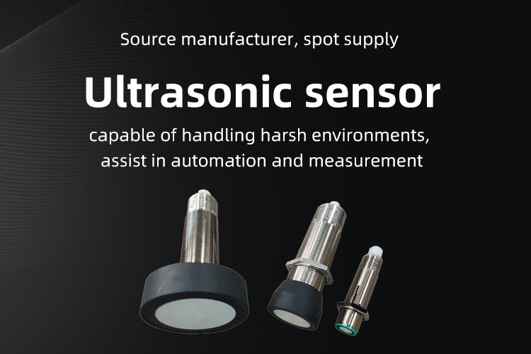
- Ultrasonic sensor
- Vehicle sensor
Vehicle sensor
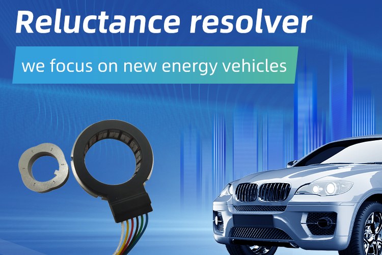
High reliability variable reluctanc resolver 101XU0440C市 场 价: ¥0元/个
优 惠 价: ¥0元/个
Parameter:
- Poles:4
- Input voltage:7VAC
- Input frequency:10KHz
- Transformation ratio:(0.286±10%)
- Accuracy: ≤±30' Max
- Phase shift:≤-15°
- Input impedance: Zro :120Ω±20%
- Output impedance: Zso:400Ω±20%
- Price: 1000+ PCS, USD16.9/PC
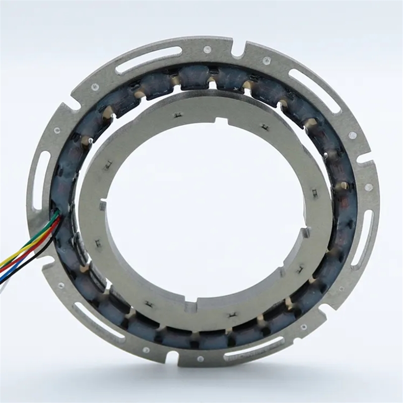
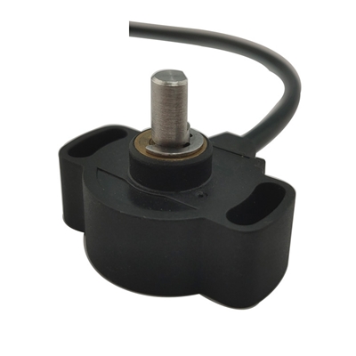
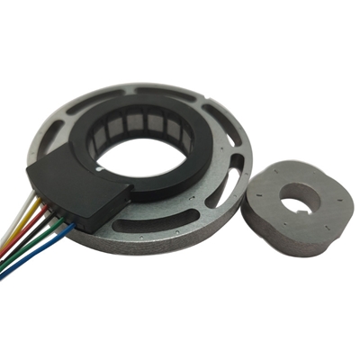
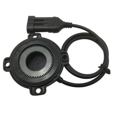
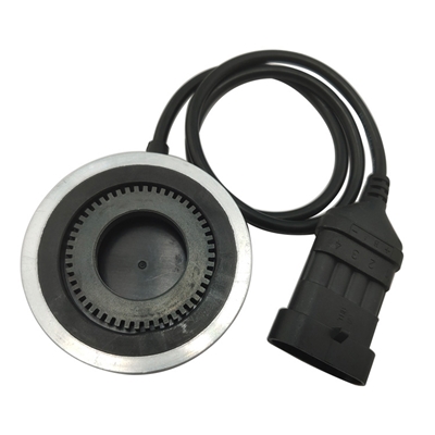
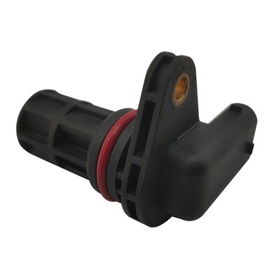
High reliability variable reluctanc resolver 101XU0440C
Product Introduction
A variable reluctance resolver is a signal element that outputs voltage that varies with the rotor angle. Under theperiodic stability of the AC magnetic field generated by the excitation winding, the rotation of the rotor causes a
change in the air gap magnetic field between the stator and rotor, which is fed back to the inductance of the
secondary winding to change, thereby inducing a change in electromotive force and forming a voltage signal,
which is converted into a digital signal (i.e. angle signal) through A/D. The product transmission signal adopts
electromagnetic induction type, which is suitable for various harsh environments, so it is widely used in military
equipment fields such as aviation, aerospace, radar, as well as industrial fields such as automobiles, robots,
metallurgical machinery, textile machinery, etc.
Characteristics:
1/High speed rotation, the speed can reach 30000 RPM
2/Low cost, maintenance free, high reliability
3/Vibration and impact resistance, protection level: IP68
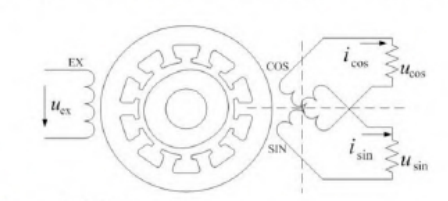
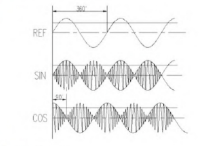
Working principle
Due to the same frequency but phase difference between the secondary voltage and the primary excitation
voltage of a rotary transformer, their amplitudes will vary as sine and cosine functions with the rotation angle.
Resolver Parameters
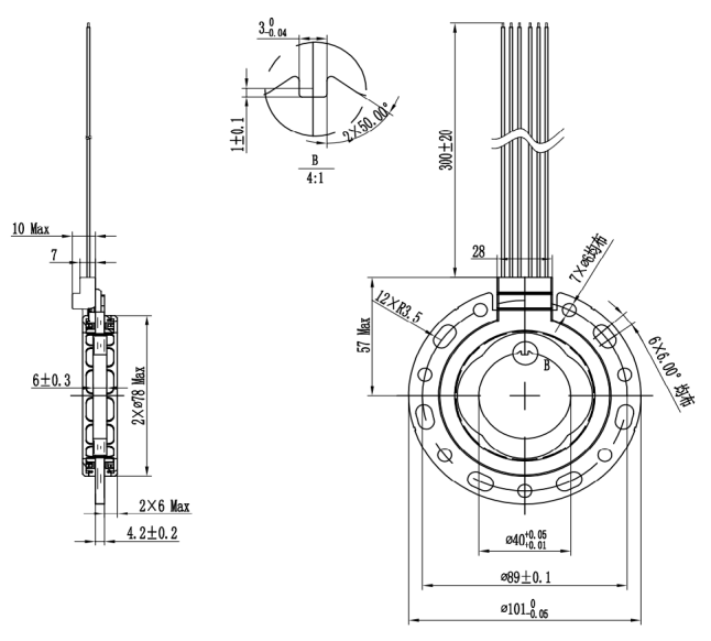
Item Parameter Remark Poles 4 Input voltage 7VAC Valid value Input frequency 10KHz Transformation ratio (0.286±10%) Accuracy ≤±30' Max Mechanical angle Phase shift ≤-7° Input impedance: Zro 100Ω±20% Output impedance: Zso TBA Dlelectric strength Ground: AC 500V 1min ≤10mA Phase: AC 500V 1min Insolution resistance 250M Ω Min DC 500V Weight ≤0.3Kg Allowable max speed 20000 rpm Working temperature -40°C~155°C Field impedance TBA Sin impedance TBA Cosin impedance TBA Single conductor² 0.35mm² UL1332 Wire 22#x6 Wire defination Ref+ Red Ref- Black Sin+ White Sin- Blue Cos+ Yellow Cos- Green Remark:
1. Winding resistance is measured at 20°C~30°C
2. Output voage equtation
US1S3=KUR1RSCOS4 ∅
US2S4=KUR1RSIN4 ∅
The positive direction is the clockwise rotation of the rotor from the outlet end
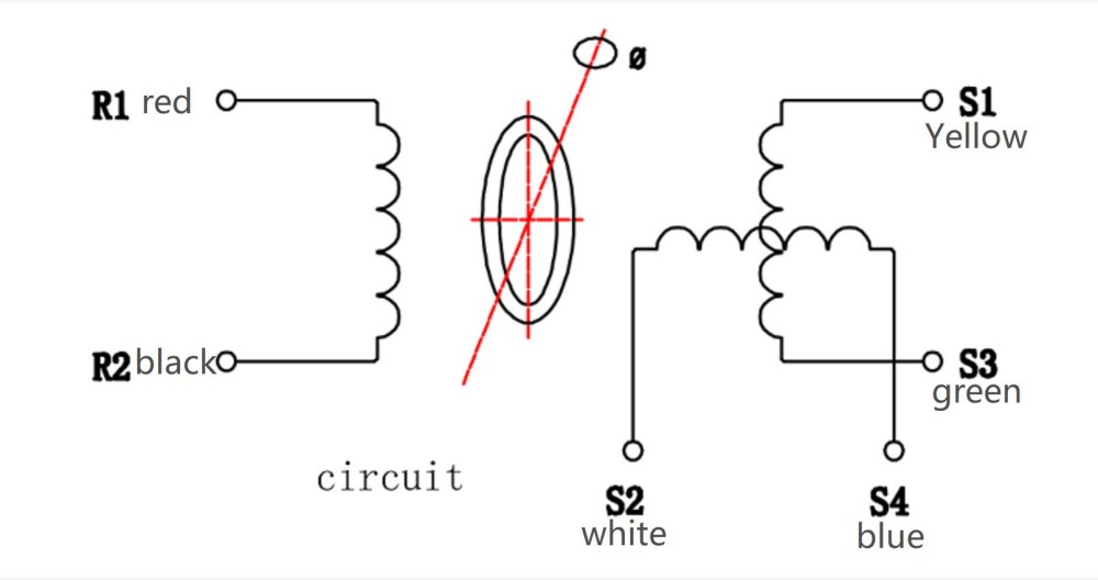
Schematic Diagrem Output wave
 Links:
Service Hotline
+86 13923792185
Website:www.micmetering.com
Address:6th Floor, Block B, Area A, Qinghu Science and Technology Park, Longhua District, Shenzhen, Guangdong Province
Copyright © 2025 MIC Metering (Shenzhen) Limited 粤ICP备2025358196号-1 Cookies Policy-
Service Hotline
Service Hotline
+86 13923792185
-
WeChat

-
TOP
Our Cookie Usage Policy
Our website uses cookies and other similar technologies to distinguish you from other users of our website. This helps us provide you with a good experience when you browse our website and allows us to improve our website. For more information, please refer to our Cookie Policy. - About Us